Jet Engine
The pulsejet project
My interest in pulsejets started many years ago, the simplicity - with the more complex designs having only one moving part appealed, not to mention the fact that they can provide significant thrust, glow red hot and make a noise so loud, you need ear plugs AND defenders when around the higher-frequency models.
There's a fair amount of material available on the internet, the most useful and informative so far beingBruce Simpson's 'aardvark' website. However, I have recently stumbled upon Beck-technologies which is possibly more useful. There has been a lot of bad press over the last few years over Bruce Simpson's poor record of sending out his CD after people having paid for it (myself included). Furthermore, some people flat out disagree with some of Bruce's opinions and ideas of pulsejets, though I am keeping an open mind.
This is a diary of my project to build a working pulsejet engine. Many online documents assume various tools are available along with materials and time. This project starts with me being unable to weld, with no experience with lathes or mills or any sort of metalwork. I have a basement, a regular set of tools mainly designed for automotive repair, some money and a whole load of enthusiasm.
I don't really see the point in creating an engine just for the sake of it. Saying you achieved X Kg of thrust doesn't provide Joe average with a real-world idea of what that means, nor is it so much fun. So, the project plan is to create a buggy/vehicle with a pulsejet strapped onto it. I originally wanted to make it radio controlled and be able to hit 100mph, but complexity and space limitations on the island might prevent this. I think a more modest approach, starting with a genuine running engine, then moving onto a vehicle once a solid design has been established would be wise.
Using various plans, I aim to create an engine with around 70 or 80lbs of thrust, hopefully adding another 10 with a thrust augmenter, which uses the outputted heat of the engine to heat fresh cool air in order to make it expand and provide an increase in thrust.
Thoughts over main areas at this stage:
-Engine
The engine itself will be created from sheet steel rolled into tubes and cones. I need to find a local steel supplier and get hold of a sheet metal roller from somewhere. Thickness of the steel will be determined when I calculate the precise dimensions of the pulsejet. The tubes and cones will be welded together using a MIG welder which appears to be the best all-rounder welding method. Currently I don't know how to weld at all, but I've signed up for a 22 week course which should show me how!
-Fuel
LPG (propane) can be used for pulsejets, but this means a heavy tank of compressed gas must be used. On the plus side there's no need for a fuel pump and battery, but on the negative there's increased weight and complexity as the radio system would have to control mechanical valves. Being a gas at room temperature also means that the fuel would mix more readily with the oxygen Jet-A jet fuel provides increased thrust over LPG apparantly, but is riskier for supplying the fuel to the engine. Methods include pressurising the fuel tank with pressure from the engine or using an electric pump. This could be highly dangerous is fuel continues to flow once the engine has stalled. The fuel is available at the local airport for a very reasonable 60p per litre, however, and is cheaper than the £25 per 11kg tank of LPG. For now I'll stick with propane.
8th October, 2006
Latest update: Research!

Well, at the minute I'm very much at the research stage of the project. There's no point blowing cash and buying equipment when I'm not 100% sure where I'm up to. So, I'm a month into becoming a qualified welder and am doing pretty well so far. Using acid tests the instructor has reliably informed me that I have good penetration, which is nice. I still want to be sure that I can make a smooth, clean weld before starting the engine build.
I'm doing a lot of reading of metalwork techniques so that I can build the engine and rolling chassis; I've also had a good read of many other other pulsejet projects to see what works and what doesn't. It looks like larger pulsjets are much easier to start which certainy is a bonus.
11th October, 2006
Latest update: Get a clever chap to help you!
So, I spoke to the instructor of my welding course who was curious as to why an IT geek wanted to learn how to weld. After describing the principals of a pulse jet, he's interested in helping me build one in the workshop if I have a few weeks spare once I've completed the actual work. Things are looking good in terms of time-scale, although I'm having trouble keeping my leg length (the width of the weld area from the join) consistant. In order to pass with distinction, I need to be able to weld 85 to 90% of a 200mm weld absolutely straight which is difficult when you're looking through a welding mask and trying to be millimeter-perfect.
Being able to use the industrial-spec hardware in the workshop would sure prove useful in making a first pulsjet. I'm looking forward to seeing what he suggests as to how to make the valve plate.
27th Feb, 2007
Changes in the first design
Only a couple of weeks left of the course, so it's really time to get my head down with this project. I've done the harder of the two test pieces and achieved distinction level, so things are looking promising. We'll see how the second piece goes tonight.
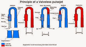
So, in order to simplify things as much as possible, I've decided to go for a valveless design, which in theory has a lot less available to wrong, and should be easier to build.
The engine will be built following Bruce Simpson's 55lbs thrust Lockwood/hiller design that is the exact model he used to win the 'rocket car' drag race in scrapheap challenge. Using a known design minimizes the number of possible errors.
Equipment.
Frustratingly, I didn't manage to get hold of a MIG rig complete with gas and auto-darkening helmet that was available second hand for an outrageously low price, so it looks like I'll be hiring a MIG rig for this project. That way I'll be able to see how it performs before committing to a particular model.
Material wise, I'll be using 1mm mild steel to start with. This has the advantage of being soft enough to shape into cones, but with sufficient strength to last apparantly 10 to 20 hours. Upon finding a design I'm happy with, I'll be moving up to stainless which is much stronger, but at a cost of being harder to work with.
I'm starting on regular propane gas to run this first engine as JET-A1 is tougher to use. Propane is a gas at regular atmospheric pressure, so it will diffuse and ignite easier. JET-A1 requires that the engine is already hot before it can be used so that the liquid fuel will vaporise. Again, this is one more area that will be tricky to get right, since the engine will have to be dual-fuel, requiring twin fuel rails and the like. It's one for future development!
Well, I've got to take time off over the next few weeks, so I'm hoping to formally start getting things going very soon. Getting this first engine cranked out will likely highlight issues that need to be sorted, so fingers crossed I have the tools and skills to put this one together!!
13th March, 2007
Qualified with distinction!
So I managed to pass the practical and written sections of the welding course to distinction level! Back of the net! Certainly time to get my butt into gear now that the weather is looking up.
16th March, 2007
Design chosen, parts coming in
Having scrapped the idea of a valved design: creating the valve plate would be complex, obtaining spring steel for the valves tricky, and choosing the correct type and thickness also adding to an already substantial list of potential failure points, the decision was made to opt for a valveless design.
 The two most popular forms of valveless engine are the U-shaped type, most notably the design made by Lockwood-Hiller in the 60's and the focused wave engine (FWE) 'chinese' style. Both have their advantages, but in general it would seem that the more popular and perhaps more compact design would be the Lockwood-Hiller.
The toughest part to find in the lockwood design is the U-pipe, which is suprisingly tricky to come by. After a fair amount of research, I've managed to pick up a galvanized steel, 100mm diameter pipe made with 0.9mm steel.
Ideally, I'd need a mandrel-drawn U or J-pipe formed from 1mm 304 stainless steel, but this is only available from performance car tuners, of which there appear to be none locally. Galv it is, then. The pipe isn't ideal, as there's a lip in it which with make the air-flow turbulent thus sapping power, but I'm hoping I'll be able to cut this out, depending on the diameters of the combustion chamber.

So, since the U-pipe is the hottest-running part of the engine, there's no need to use harder to work wtih stainless to build the rest, and I'll be able to stick with mild or galv, depending on costs. A note to all using galvanized steel: when welding/heating, the zinc layer produced noxious fumes, so make sure it's put together in a ventialted workshop, and of course run the engine outside somewhere.
I'm hoping to pick up a half sheet of steel tomorrow, along with some appropriate tools for cutting and forming the stuff. I've booked monday off work, and I hope to have gotten far enough to start sticking bits together by then!
18th March, 2007
Planning the shapes and sizes
Considering the toughest parts to get hold of are the bends, the rest of the design pretty much hinged on what I could find. With the bend in hand, I was able to grab some plans for Simpson's 55lbs Lockwood hiller, and scale them to the pipe I had. A few basic calculations later, and I had my dimensions sketched out.
With my less than super-detailed plans sorted, I was eager to get on the case with this thing. An awesome application availbale online helped me map out the templates for the cones. Simply punch in the numbers and hit print. Cut out the pieces of templatre and stick together nice and carefully over a beer. A great sunday in.
Finally, I can see this project coming together.
So, scaling directly upwards from Bruce's design, my engine theoretically would be able to push out 73lbs of thrust. That's quite a lot.


19th March, 2007
Cranking out parts

The local metal supplier is only 100 meters from my house, so along with my trusty sidekick Joe, I grabbed a 1 x 2m sheet of hot-rolled, 22guage (~1mm thick) mild steel. I believe the pipe is 0.9mm, but they didn't have 22 guage available. This being my first prototype, 0.1mm differences weren't going to be too important.
After a good clean down to remove the oil on the sheet, I picked up my newly purchased bad-ass grinder and lobbed the sheet into four pieces for the major areas. Next up, we grabbed a decent ruler, some tape and a marker, and went ahead marking all the shapes out. Measuring up afterwards and everything was millimeter accurate to the original plans. So far so good.
Later on, I went into the garage and spent a couple of hours grinding and filing out the shapes. I didn't have enough time to do the inside of the small arcs. but I'm hoping to do this tonight at the workshop. This evening I aim to finish the edges, roll the cones and hopefully get at least some of it welded together.
The consideration for tonight will be to see how close the main outlet pipe comes to the combustion chamber. If there's enough space (also considering space for mounting brackets) I'm hoping to grind away some of the metal on the galvanized pipes to make the curve tighter. There's also a couple of lips that will make the airflow inside slightly more turbulent, which will waste energy. If I can, I'll get rid of these.
Still got to sort out the fuel pipe and assosciated connections. The guy in the gas store looked at me funny last time I tried to get hold of the asociated parts. I need to find some screw-on fitting and the thread type so I can create a fuel pipe to fit. This could be tricky.


20th March, 2007
Formed and ready to weld
The insides of the curves were impossible to do with a grinder, so in the welding workshop I got my hands on a pair of tin snips, that with a little work can form some damned good curves. Apparantly you can go up to 1.5mm stainless with snips, though I don't know if my nerdy hands would have the strength. Each piece was carefully filed and ground to give it a nice tight edge. I then got to work with the pinch roller and started rolling the metal. Having never used a roller before t was quite an experience. It's not so bad with the 0.9mm mild steel I used, but once the evening classes are over and I no longer have acccess to industrial-sized rollers, it's going to be a bugger to form the neccessary shapes. That's one to solve in the future.Three hours in the class got me quite far, but I didn't get to tack weld the parts togehter which is a bit of a bummer. It would have been good to do so, so I could perfect the shapes in my own time before welding the lot together.
I'm pretty damned happy with the outcome, though the size of this thing is begining to dawn on me!


Onto the intarweb I went and spent a few hours researching. Here's what I know: I need to use screw-in LPG gas bottles (easily obtainable locally without licence). Instead of using a regulator (converts tank pressure to low output pressure/flow), I need what is known as a 'pigtail' connector, which plugs directly into the tank. The output of this is high pressure. From this, I'm going to use a ball-valve which will allow the gas-flow to be turned off in an instant. The other side of the ball valve will connect to a quarter-inch copper tubing, which will then fit somehow to a fuel fail that I'm yet to put togehter. Could be tricky.
This site was damned helpful in sourcing parts for the gas. I'll update on whether this setup works. The next major problem could also be that modern tanks don't physically allow gas to flow out of them quick enough; there's a safety valve that stops you from fliping it over and letting liquid gas flow out the pipe. Fingers crossed I can get around this somehow, otherwise I'll be running my engine at, or just above idle, which is less than ideal.
I'm also begining to throw some ideas togehter as to how to mount this bad-boy, and some kind of vehicle on which to mount it. I'll upload some doodles I made, perhaps.
27th March 2007
Welding woes!
I picked up a rental 130amp MIG rig from the local hire shop early today and went up to joe's to start putting this puppy together. Using Ivan's (a friend who works at a steel fab company) help, we started tacking the sections together so we could check for fit before welding everything. We had nothing but trouble from the antiquated rig, however. The welding torch, contact tip and shroud were all knackered. It leaked gas, and the filler wire was also shoddy. We managed to get most things tacked up, when the crappy (and stupidly expensive) disposable gas canister expired. Feeling cheated, we returned to the shop, got a refund and went on the prowl for another rig. A local supplier had an awesome offer which included a freebee £200 welding mask, but they were out. A buddy who said he'd lend me a rig was also out of his shop, so we decided it just wasn't meant to be.We grabbed a coil for starting the engine from a crappy SJ410 at the scrap yard, then picked up some meat and had a barbeque instead.
The evening came and I went to my welding course with my parts. The industrial sized rig they use in the class has 1.0mm filler wire in it that was just pushing through all the test pieces I tried and was just a waste of time. The instructor wheeled in a 185amp Sealey rig using 0.8mm wire. It was still a nightmare to weld without burning through, and theonly method I got to work properly meant I I had to weld in maybe 4mm long strips, as well as stitch welding in order to reduce overall temperature.
Eventually I got all the bits welded together, but it needs shaping and assembling. One final problem is that I mapped out one of my cones incorrectly such that it is 20mm too large. I can trim this down, but it does mean that the angle of the cone is 11 degrees steeper than it should be. Not so good. I'm in two minds as to whether to live with it or pick up more steel and remake the part.
Everything needs grinding down, but it's looking pretty solid now. Over the next few days, I'll shape and grind everything so it's ready to put togehter when I next get my hands on a welding rig.


28th March 2007
I've got gas... parts.
Neato, the high pressure gas parts arrived! I set to work straight away 'modifying' (hacksaw + drill) them to fit each other. I have a nasty feeling I may need a slightly more uprated ball valve as this one seems a tad small, and can only cope with 20Bar of pressure whereas the chap at the gas store claims a regular propane tank can squeeze out 35Bar. Pretty high pressures. I also need to get a couple of jubilee clips to hold that hose in place, and will allow me to remove the gaffer tape that's holding the braiding together.I also took a photo of the coil. I looks pretty tired, but nothing that 10 minutes with a wire brush won't fix.
I'm hoping to borrow a MIG welder this weekend. I've decided that since I need to pick up some more sheet steel for the augmentors, I'm going to rebuild the cone that is slightly out. It's annoying, as the cone itself came out really well. I don't want it on the back of mind, however, if this thing refuses to start or run.


22nd April 2007
Fuel Rail
After a bit of a delay, I'm very much back into the swing of things with the pulsejet. I've just not been updating the site as often as I should.So where am I at? The jet is mostly welded together. The problem with the poorly fitting part was the result of my creating one of the cones incorrectly, though it transpires that it was the first come that I created and hence was formed quite poorly, so I'm not overly upset. I've cut it out and ordered more steel in order to get a decent replacement.
In terms of steel, it looks like stainless is nothing short of damned expensive! I bought a 3x8 foot sheet of 20-guage (0.91mm) thick mild steel for £18 (;£14 trade). The same sized sheet of stainless will set me back in the order of £80-100. That's some difference. I'll certainly have to make a prototype out of mild before blowing that kind of cash on stainless.
So what have I been up to? Well, good and bad news on the gas front. The 'pigtail' connector and mini ball valve look like they're not going to do. The valve doesn't look like it can take the pressure, and also appears to work with gas flowing in one direction only, which of course is the opposite direction that I need. Finally, the 'output' of the valve is 6mm, whereas I need 8mm connections. The chap in the gas store seems to have taken a dislike to me, and continues to refuse to sell me parts, despite a legal waiver clearly mounted on the desk, and my willingness to sign whatever it takes for me to be able to take responsibility for my own actions. Somewhere I need to source another pigtail that goes into a more industrial ball valve with an 8mm compression fitting output.
On the other hand, I have managed to source the fittings from another plumbing supplier to fit onto the fuel rail which I created:
First up, I bought a 1m long 8mm OD (outer diameter) pipe from the local B&Q. They also had a drill mount available at discount for only £13 which I picked up. It's very far from perfect, but does make life a bit easier when drilling. I drilled two rows of four 1mm holes right the way through at 90 degrees, resulting in 16 holes. I then took a small piece of sheet metal and welded up the end of the rail to form a seal.
On the other end, I used a die (a device to thread metal, allowing you to screw on parts) to add a thread. The die was actually quite expensive, at about £4 for the ¼" x 19mm BSP threaded model that I needed for the gas fittings.
The gas fittings were a bit of a hodgepodge, but allow me to do the necessary. FYI they are:
A straight coupling, 10x8
Brass plain socket, 1/4"
Brass hex bushes, 3/8" x 1/4"
A couple of bits don't get used, but the rest of it screws together to form a decent connection.


I want the fuel rail to be adjustable to allow me to alter the depth into the engine that the fuel is introduced. This apparently makes a large difference to the running of the engine. The second advantage to this rail design is that if it's generally just no good,, I'll be able to throw it out and start over. On the negative side, the rail itself will disrupt airflow, thus sapping some power.
To support the rail, I cut some more 2mm steel bar, bent it to shape as below. It seems to work pretty well, though the steel isn't quite as springy as one might like, but I think it will do the job just great. I need to grind down the welds some more to smoothen it all out, but I'm pretty happy with it.


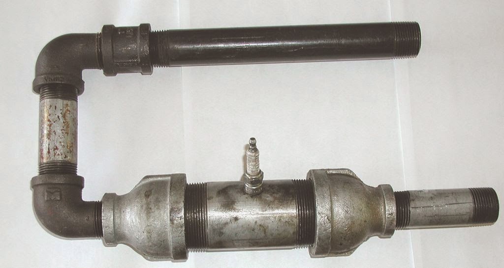
It's all pretty much in place now. I've got a photo here of the beast before I took the dodgy cone out. As I type this, I need to cut and roll (somehow...) one cone, and weld it into position before the engine is effectively finished. There's also a pic of the welding rig I picked up. £320 bought me a fantastic 150amp MIG with a special offer of a £200 electric welding mask thrown in. The mask to me is better that the Speedglas one at the welding workshop which is considered to be the Rolls-Royce of masks:


pulse jet engine Photos :